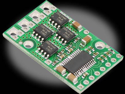
The High Power Motor Driver is a discrete MOSFET H-bridge designed to drive large DC brushed motors. The H-bridge is made up of one N-channel MOSFET per leg, and most of the board’s performance is determined by these MOSFETs (the rest of the board contains the circuitry to take user inputs and control the MOSFETs). The MOSFETs have an absolute maximum voltage rating of 30V, and higher voltages can permanently destroy the motor driver. Under normal operating conditions, ripple voltage on the supply line can raise the maximum voltage to more than the average or intended voltage, so a safe maximum voltage is approximately 24V.
Note: Battery voltages can be much higher than nominal voltages when they are charged, so the maximum battery voltage we recommend is 36V unless appropriate measures are taken to limit the peak voltage.
The versatility of this driver makes it suitable for a large range of currents and voltages: it can deliver up to 9A of continuous current with a board size of only 1.3 by 0.8in. and no required heat sink. With the addition of a heat sink, it can drive a motor with up to 12A of continuous current. The module offers a simple interface that requires as little as two I/O lines while allowing for both sign-magnitude and locked-antiphase operation. Integrated detection of various short-circuit conditions protects against common causes of catastrophic failure; however, please note that the board does not include reverse power protection or any over-current or over-temperature protection.
Using the Motor Driver
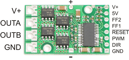
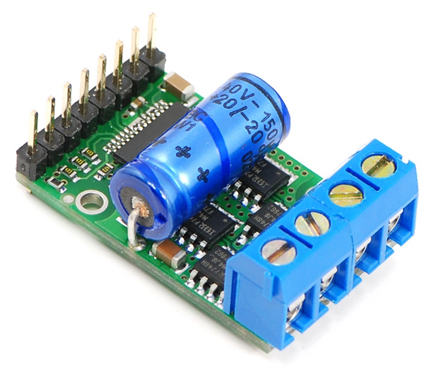
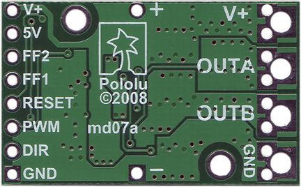
The motor and motor power connections are on one side of the board, and the logic (control) connections are on the other side. The motor supply should be capable of supplying high current, and a large capacitor should be installed close to the motor driver. The included axial capacitor can be installed directly on the board in the pins labeled '+' and '-' as shown below. Such installations are compact but might limit heat sinking options; also, depending on the power supply quality and motor characteristics, a larger capacitor might be required. There are two options for connecting to the high-power signals (V+, OUTA, OUTB, GND): large holes on 0.2in. centers, which are compatible with the included terminal blocks, and pairs of 0.1in.-spaced holes that can be used with perfboards, breadboards, and 0.1in. connectors.
Warning: Take proper safety precautions when using high-power electronics. Make sure you know what you are doing when using high voltages or currents!
In a typical configuration, only PWM and DIR are required. Note that the voltage on these inputs must be higher than 3.5V to be guaranteed to register as high, so we do not recommend connecting this device directly to a 3.3V controller. The two fault flag pins (FF1 and FF2) can be monitored to detect problems. The RESET pin, when held low, puts the driver into a low-power sleep mode and clears any latched fault flags. The V+ pin on the logic side of the board gives you access to monitor the motor’s power supply (it should not be used for high current). The board also provides a regulated 5V pin which can provide a few milliamps (this is typically insufficient for a whole control circuit but can be useful as a reference or for very low-power microcontrollers).
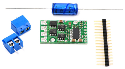
Included Hardware
A 16-pin straight breakaway male header, one 100 uF capacitor, and two 2-pin 5mm terminal blocks are included with each motor driver. Connecting a large capacitor across the power supply is recommended; one way to do it is between the '+' and '-' holes.
Motor Control Options
With the PWM pin held low, both motor outputs will be held low (a brake operation). With PWM high, the motor outputs will be driven according to the DIR input. This allows two modes of operation: sign-magnitude, in which the PWM duty cycle controls the speed of the motor and DIR controls the direction, and locked-antiphase, in which a pulse-width-modulated signal is applied to the DIR pin with PWM held high.
In locked-antiphase operation, a low duty cycle drives the motor in one direction, and a high duty cycle drives the motor in the other direction; a 50% duty cycle turns the motor off. A successful locked-antiphase implementation depends on the motor inductance and switching frequency smoothing out the current (e.g. making the current zero in the 50% duty cycle case), so a high PWM frequency might be required.
PWM Frequency
The motor driver supports PWM frequencies as high as 40 kHz, though higher frequencies result in higher switching losses in the motor driver. Also, the driver has a dead time (when the outputs are not driven) of approximately 3 us per cycle, so high duty cycles become unavailable at high frequencies. For example, at 40 kHz, the period is 25 us; if 3 us of that is taken up by the dead time, the maximum available duty cycle is 22/25, or 88%. (100% is always available, so gradually ramping the PWM input from 0 to 100% will result in the output ramping from 0 to 88%, staying at 88% for inputs of 88% through 99%, and then switching to 100%.)
Real-World Power Dissipation Considerations
The motor driver can handle large current spikes for short durations (e.g. 100A for a few milliseconds). The peak ratings are for quick transients (e.g. when a motor is first turned on), and the continuous rating of 9A is dependent on various conditions, such as the ambient temperature. The actual current you can deliver will depend on how well you can keep the motor driver cool. The driver’s printed circuit board is designed to draw heat out of the MOSFETs, but performance can be improved by adding a heat sink. With a heat sink the motor driver can be run at up to 12A of continuous current.
Warning: This motor driver has no over-current or over-temperature shut-off. Either condition can cause permanent damage to the motor driver.
Fault Conditions
The motor driver can detect three different fault states, which are reported on the FF1 and FF2 pins. The detectable faults are short circuits on the output, under-voltage, and over-temperature. A short-circuit fault is latched, meaning the outputs will stay off and the fault flag will stay high, until the board is reset (RESET brought low). The under-voltage fault disables outputs but is not latched. The over-temperature fault provides a weak indication of the board being too hot, but it does not directly indicate the temperature of the MOSFETs, which are usually the first components to overheat. The fault flag operation is summarized below.
| Flag State |
| FF1 |
FF2 |
Fault Description |
Disable Outputs |
Latched Until Reset |
| L |
L |
No Fault |
No |
No |
| L |
H |
Short Circuit |
Yes |
Yes |
| H |
L |
Over Temperature |
No |
No |
| H |
H |
Under Votalge |
Yes |
No |
| Specs |
| Motor Driver |
IRF7862PbF MOSFETs |
| Motor Channels |
1 |
| Minimum Operating Voltage |
5.5V |
| Maximum Operating Voltage |
30V |
| Continuous Output Current Per Channel |
15A |
| Peak Output Current Per Channel |
170A |
| Maximum PWM Frequency |
40 kHz |
| MOSFET on-resistance (per leg) |
3.7 mΩ |
| Reverse Voltage Protection |
No |
| Size |
1.3 x 0.8in. |


 User's Manual