0-OSMC OSMC Speed Controller <p align="left"><font color="00ff66" size="2" face="Arial, Helvetica, sans-serif">The OSMC is
a high-power H-bridge circuit designed to control permanent magnet DC motors.
It was designed expressly as a motor control for robot combat in competitions
such as BattleBots™, Robot Wars™, Robotica™, and the like.
The attributes of a controller for such an environment are much different
than normally found in commercial or industrial motor control units. A robotic
combat controller must have very high short-term power handling capability
along with light weight and simple interfacing. It must drive a wide variety
of motors and be easy to mount and secure from the shock and vibration of
combat. The ideal controller should also be low-cost and easy to repair if
needed.</font></p>
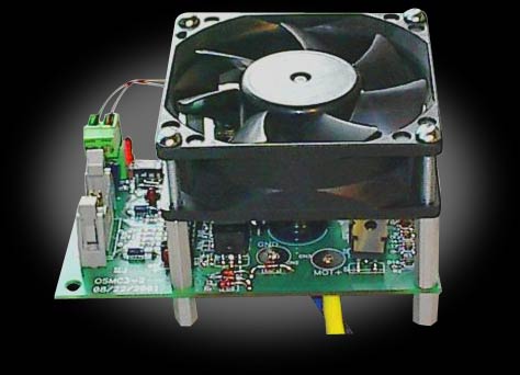
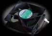
<p><font color="00ff66" size="2" face="Arial, Helvetica, sans-serif"> Unlike most motor controls
the OSMC does not use a heavy heatsink to extract heat from the MOSFETs.
Rather, it uses a cooling fan to blow air across the board. This removes
more heat more quickly than a plate type heatsink as has lower weight. The
fan itself is a commonly available 80mm square computer cooling fan. Either
a 12V or 24V fan may be installed on the OSMC. Mounting holes are provided
at the correct spacing to mount the fan directly over the MOSFETs for maximum
cooling efficiency.<br>
<br>
The OSMC is a "simple" H-bridge power amplifier. It does not have
any on-board logic to interpret RC or other commands. An external logic interface
is required to translate command inputs into the PWM signals needed to drive
the board. This increases system complexity somewhat but also increases flexibility
as the OSMC board may be driven by any microcontroller or other signal source
that can provide PWM and Enable logic. The OSMC project has developed the Modular
OSMC Brain board to complement and complete the OSMC power board. This microcontroller-based
interface board accepts RC signals and performs the conversion to PWM for two
OSMC boards.<br>
<br>
One of the major advantages of separating the power section of the controller
from the logic interface section is to allow the power units to be paralleled
for special applications. One exciting application of this is to use two OSMC
boards on a single interface channel to control high-powered four-brush motors
such as the Ampflow or Astroflight™ motors.
By using a special interface cable the OSMC can control these 4-brush motors
at twice the current of a single power unit. That gives a continuous current
capability of over 300A! <a href="htttp://robotcombat.com/products/images/store_osmccombo.jpg">This image</a> shows
2 OSMC boards driving a four inch Ampflow Motor. Stall testing with this motor and
24V of Hawker batteries showed no appreciable heating of the OSMC boards. </font></p>
<p><font color="00ff66" size="2" face="Arial, Helvetica, sans-serif">The method used by the
OSMC/µRRC is superior to using two R/C-based controllers such as IFI
Victor/Thor or Vantec on a four-brush motor because with the OSMC the two
power units are driven by exactly the same drive signals and they will switch
in perfect synchronization. Two RC-based controllers connected using a Y-cable
to will not have the controllers synchronized due to differences between
them. Clearly the OSMC is the way to go for maximum power handling on these
large powerful motors. </font></p>
<p><font color="#CCCCCC" size="2" face="Arial, Helvetica, sans-serif">For some
related downloadable files regarding the OSMC, see the <a href="http://www.robot-power.com/downloads/">download
page</a>.</font></p>
<table border="1" cellpadding="0" cellspacing="0" bordercolor="#666666">
<tr>
<td width="151"><font color="#CCCCCC" size="2" face="Arial, Helvetica, sans-serif">Supply
voltage</font></td>
<td width="275"><font color="#CCCCCC" size="2" face="Arial, Helvetica, sans-serif">13V
to 50V</font></td>
</tr>
<tr>
<td><font color="#CCCCCC" size="2" face="Arial, Helvetica, sans-serif">Output
Current (continuous)</font></td>
<td><font color="#CCCCCC" size="2" face="Arial, Helvetica, sans-serif">160A</font></td>
</tr>
<tr>
<td><font color="#CCCCCC" size="2" face="Arial, Helvetica, sans-serif">Output
Current (surge)</font></td>
<td><font color="#CCCCCC" size="2" face="Arial, Helvetica, sans-serif">>400A</font></td>
</tr>
<tr>
<td><font color="#CCCCCC" size="2" face="Arial, Helvetica, sans-serif">Weight</font></td>
<td><font color="#CCCCCC" size="2" face="Arial, Helvetica, sans-serif">0.6
lb</font></td>
</tr>
<tr>
<td><font color="#CCCCCC" size="2" face="Arial, Helvetica, sans-serif">MOSFETs</font></td>
<td><font color="#CCCCCC" size="2" face="Arial, Helvetica, sans-serif">16
ea. IRF 1404 or 1405</font></td>
</tr>
<tr>
<td><font color="#CCCCCC" size="2" face="Arial, Helvetica, sans-serif">On
Resistance</font></td>
<td><font color="#CCCCCC" size="2" face="Arial, Helvetica, sans-serif">.0010
ohm max 1404<br>
.0013 ohm max 1405 </font></td>
</tr>
<tr>
<td><font color="#CCCCCC" size="2" face="Arial, Helvetica, sans-serif">Cooling</font></td>
<td><font color="#CCCCCC" size="2" face="Arial, Helvetica, sans-serif">40
CFM fan</font></td>
</tr>
<tr>
<td><font color="#CCCCCC" size="2" face="Arial, Helvetica, sans-serif">Bridge
Driver</font></td>
<td><font color="#CCCCCC" size="2" face="Arial, Helvetica, sans-serif">Intersil
HIP4081A</font></td>
</tr>
<tr>
<td><font color="#CCCCCC" size="2" face="Arial, Helvetica, sans-serif">Logic
Interface</font></td>
<td><font color="#CCCCCC" size="2" face="Arial, Helvetica, sans-serif">10-pin
dual-row header</font></td>
</tr>
<tr>
<td><font color="#CCCCCC" size="2" face="Arial, Helvetica, sans-serif">Power
Supply</font></td>
<td><font color="#CCCCCC" size="2" face="Arial, Helvetica, sans-serif">12V
.5A regulator</font></td>
</tr>
<tr>
<td><font color="#CCCCCC" size="2" face="Arial, Helvetica, sans-serif">Current
Limiting</font></td>
<td><font color="#CCCCCC" size="2" face="Arial, Helvetica, sans-serif">Optional
Add-on </font></td>
</tr>
<tr>
<td><font color="#CCCCCC" size="2" face="Arial, Helvetica, sans-serif">Connectors</font></td>
<td><font color="#CCCCCC" size="2" face="Arial, Helvetica, sans-serif">Solder
pads for up to 10 ga wire</font></td>
</tr>
<tr>
<td><font color="#CCCCCC" size="2" face="Arial, Helvetica, sans-serif">Enclosure</font></td>
<td><font color="#CCCCCC" size="2" face="Arial, Helvetica, sans-serif">Under
development</font></td>
</tr>
</table>
<p><font color="ff0000" size="2" face="Arial, Helvetica, sans-serif">Please note: These controllers are now built upon receipt of order. This may take up to 7 days before the controller is shipped.</font></p>
PLEASE NOTE: There is no fan included with this OSMC. If you want a fan, you
will need to add your choice of a 12V or 24V fan.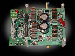
 $219.00
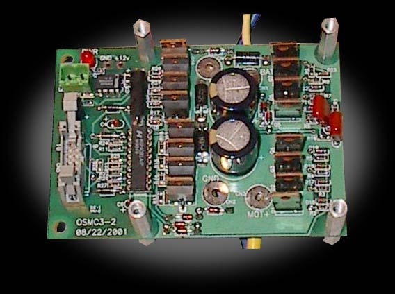


 12V Fan Kit for OSMC
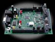 Dalf Dual Advanced Closed-Loop Motor Control